Robots
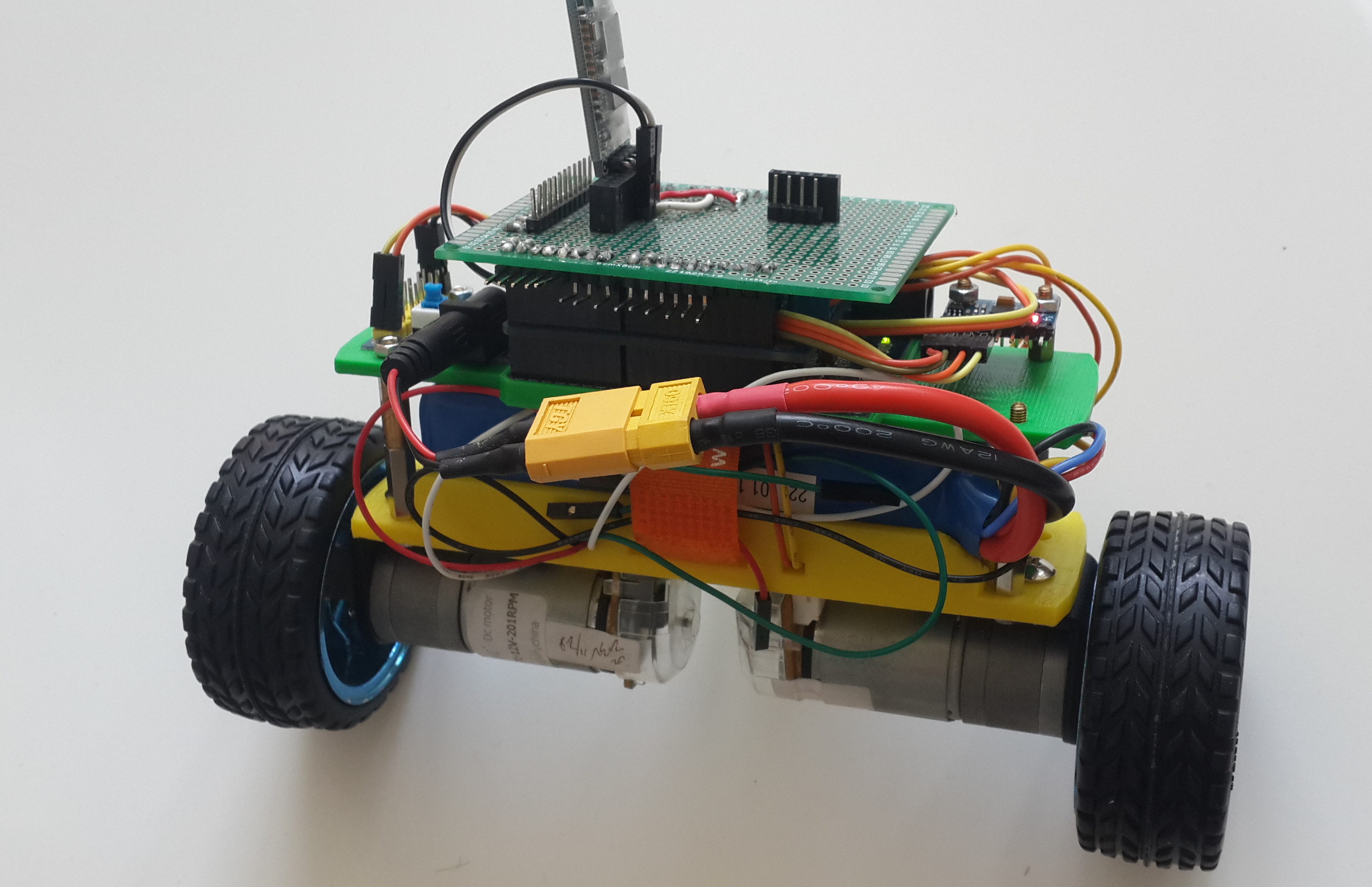
Home-made Self-balance Robot
During my free time I built this robot which can balance itself on two wheels and can handle small disturbance. Further work shall be done on remote controlling to move it.
The objective is to have some hands-on with proccessing the data of an inertia sensor, and also implementing the PID controller to have some insight of how PID works. In the end, of course, to have some fun!
Code: Github Repo
»Demo
»Hardwares
- Arduino Leonardo Board
- 2 DC Motors: JGA25-371 with encoders
- Arduino Motor Driver Shield
- 12V-5V-3.3V Power Convertion Board
- ZIPPY Flightmax 2200mAh 3S1P 25C Battery
- HC-06 BlueTooth Module
- MPU-6050 6DOF IMU
- Self designed 3D-printed robot structure (on thingiverse)
»Pin Connection
Refer to motor.h. Leonardo Serial1 is used to connect the Bluetooth.
»Dependency
MPU6050 lib from i2cdevlib and arduino-pinchangeint. You need to place the libs in the ~/sketchbook/libraries/ folder
»Software Key Components
Kalman filter: to fuse the data from accerometer and gyro and output angle. The implementation is referenced from TKJElectronics’s Balanduino.
PID control: “velocity” PID which can prevent integral windup (Further theory refer to this link). Target is to stablize the robot around angle 0.
Tune PID via Bluetooth: I downloaded BlueTerm to pair and communicate with arduino. Can Tune the PID without wire.
Motor control: control use PWM signal, a bit tuning is done to make both motors run at same RPM given same PWM value. And the motor has a minimum PWM to be applied, because under certain minimum PWM value the motor does not move at all.
Python Debug: python script analysis/serial_plot.py can plot the data from Serial port in real time. But the message has to follow the format “name\t value\t name\t value\t…\n”
»Problem encountered
Initially, becuase I place the IMU with its x-axis pointing forward. So I was calculating the angle of the robot using x and z axis of the accerometer, along with the angle accumulated from gyro in x-axis, but that’s wrong! I should use gyro in y-axis, because rotating around y axis correspond to leaning forward.
This motor can not supply enough torque when the robot deviate its angle too much, so the robot can still fall down when angle error is big.
DESIGN
robot arduino pid kalman filter